instructions for electromagnetic single disc brakes 4.62
Anuncio
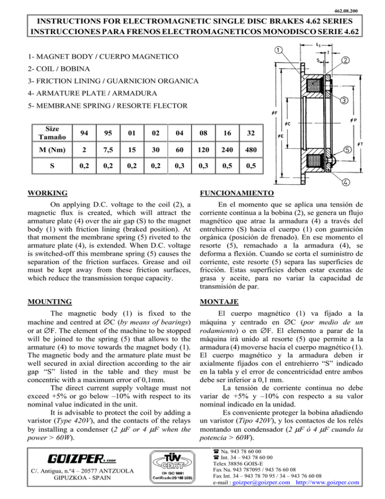
462.08.200 INSTRUCTIONS FOR ELECTROMAGNETIC SINGLE DISC BRAKES 4.62 SERIES INSTRUCCIONES PARA FRENOS ELECTROMAGNETICOS MONODISCO SERIE 4.62 1- MAGNET BODY / CUERPO MAGNETICO 2- COIL / BOBINA 3- FRICTION LINING / GUARNICION ORGANICA 4- ARMATURE PLATE / ARMADURA 5- MEMBRANE SPRING / RESORTE FLECTOR Size Tamaño 94 95 01 02 04 08 16 32 M (Nm) 2 7,5 15 30 60 120 240 480 S 0,2 0,2 0,2 0,2 0,3 0,3 0,5 0,5 WORKING FUNCIONAMIENTO On applying D.C. voltage to the coil (2), a magnetic flux is created, which will attract the armature plate (4) over the air gap (S) to the magnet body (1) with friction lining (braked position). At that moment the membrane spring (5) riveted to the armature plate (4), is extended. When D.C. voltage is switched-off this membrane spring (5) causes the separation of the friction surfaces. Grease and oil must be kept away from these friction surfaces, which reduce the transmission torque capacity. En el momento que se aplica una tensión de corriente continua a la bobina (2), se genera un flujo magnético que atrae la armadura (4) a través del entrehierro (S) hacia el cuerpo (1) con guarnición orgánica (posición de frenado). En ese momento el resorte (5), remachado a la armadura (4), se deforma a flexión. Cuando se corta el suministro de corriente, este resorte (5) separa las superficies de fricción. Estas superficies deben estar exentas de grasa y aceite, para no variar la capacidad de transmisión de par. MOUNTING MONTAJE The magnetic body (1) is fixed to the machine and centred at ∅C (by means of bearings) or at ∅F. The element of the machine to be stopped will be joined to the spring (5) that allows to the armature (4) to move towards the magnet body (1). The magnetic body and the armature plate must be well secured in axial direction according to the air gap “S” listed in the table and they must be concentric with a maximum error of 0,1mm. The direct current supply voltage must not exceed +5% or go below –10% with respect to its nominal value indicated in the unit. It is advisable to protect the coil by adding a varistor (Type 420V), and the contacts of the relays by installing a condenser (2 µF or 4 µF when the power > 60W). El cuerpo magnético (1) va fijado a la máquina y centrado en ∅C (por medio de un rodamiento) o en ∅F. El elemento a parar de la máquina irá unido al resorte (5) que permite a la armadura (4) moverse hacia el cuerpo magnético (1). El cuerpo magnético y la armadura deben ir axialmente fijados con el entrehierro “S” indicado en la tabla y el error de concentricidad entre ambos debe ser inferior a 0,1 mm. La tensión de corriente continua no debe variar de +5% y –10% con respecto a su valor nominal indicado en la unidad. Es conveniente proteger la bobina añadiendo un varistor (Tipo 420V), y los contactos de los relés montando un condensador (2 µF ó 4 µF cuando la potencia > 60W). C/. Antigua, n.º4 – 20577 ANTZUOLA GIPUZKOA - SPAIN Na. 943 78 60 00 Int. 34 – 943 78 60 00 Telex 38856 GOIS-E Fax Na. 943 787095 / 943 76 60 08 Fax Int. 34 – 943 78 70 95 / 34 – 943 76 60 08 e-mail : [email protected] http://www.goizper.com 463.08.200 INSTRUCTIONS FOR ELECTROMAGNETIC SINGLE DISC BRAKES 4.63 SERIES INSTRUCCIONES PARA FRENOS ELECTROMAGNETICOS MONODISCO SERIE 4.63 1- MAGNET BODY / CUERPO MAGNETICO 2- COIL / BOBINA 3- FRICTION LINING / GUARNICION ORGANICA 4- ARMATURE PLATE / ARMADURA 5- MEMBRANE SPRING / RESORTE FLECTOR 6- HUB / MOYU M ∅C (Nm) Tamaño H8 94 2 18 95 7,5 35 01 15 42 02 30 52 04 60 62 08 120 80 16 240 100 32 480 125 Size ∅ E ∅F h9 52 62 72 83 90 100 112 125 138 150 175 190 215 230 270 290 ∅P ∅ T b ∅emax ∅m 29 46 60 76 95 120 158 210 12 15 20 25 30 38 48 55 42 63 80 100 125 160 200 250 10 15 20 30 35 50 65 80 18,5 27 38 42 52 65 83 105 l1 S 33 37 44,7 53,1 61,1 72,6 89 102,5 0,2 0,2 0,2 0,2 0,3 0,3 0,5 0,5 WORKING On applying D.C. voltage to the coil (2), a magnetic flux is created, which will attract the armature plate (4) over the air gap (S) to the magnet body (1) with friction lining (braked position). At that moment the membrane spring (5), riveted to the armature plate and to the hub (6), is extended. When D.C. voltage is switched-off this membrane spring causes the separation of the friction surfaces. Grease and oil must be kept away from these friction surfaces, which reduce the transmission torque capacity. FUNCIONAMIENTO En el momento que se aplica una tensión de corriente continua a la bobina (2), se genera un flujo magnético que atrae la armadura (4) a través del entrehierro (S) hacia el cuerpo magnético (1) con guarnición orgánica (posición de frenado). En ese momento el resorte (5), remachado a la armadura y al moyú (6), se deforma a flexión. Cuando se corta el suministro de corriente este resorte separa las superficies de fricción. Estas superficies deben estar exentas de grasa y aceite, para no variar la capacidad de transmisión de par. MOUNTING The magnetic body (1) is bolted at ∅E and centred at ∅C (by means of bearings) or at ∅F. This body must be concentric to the hub at ∅e with a maximum error of 0,1mm. The armature plate (4) is joined to the hub (6) by the membrane spring to allow a free movement. The hub (at b) and the body (1) must be well secured in axial direction with the air gap in conformity with the dimension “S” listed in the table. Take note of the mounting dimension “l1” to adjust the air gap. The direct current supply voltage must not exceed +5% or go below –10% with respect to its nominal value indicated in the unit. It is advisable to protect the coil by adding a varistor (Type 420V), and the contacts of the relays by installing a condenser (2 µF or 4 µF when the power > 60W). MONTAJE El cuerpo magnético (1) va atornillado en ∅E y centrado en ∅C (por medio de un rodamiento) o en ∅F. El error de concentricidad del cuerpo con respecto al ∅e del moyú debe ser inferior a 0,1mm. La armadura (4) va unido al moyú (6) con un resorte que le permite moverse libremente. El moyú (en b) y el cuerpo (1) deben estar axialmente fijados con el entrehierro “S” requerido (indicado en la tabla). Para el ajuste de los entrehierros debe ser tenida en cuenta la medida “l1”. La tensión de corriente continua no debe variar de +5% y –10% con respecto a su valor nominal indicado en la unidad. Es conveniente proteger la bobina añadiendo un varistor (Tipo 420V), y los contactos de los relés montando un condensador (2 µF ó 4 µF cuando la potencia>60W). C/. Antigua, n.º4 – 20577 ANTZUOLA GIPUZKOA - SPAIN Na. 943 78 60 00 Int. 34 – 943 78 60 00 Telex 38856 GOIS-E Fax Na. 943 787095 / 943 76 60 08 Fax Int. 34 – 943 78 70 95 / 34 – 943 76 60 08 e-mail : [email protected] http://www.goizper.com 464.08.200 INSTRUCTIONS FOR ELECTROMAGNETIC SINGLE DISC BRAKES 4.64 SERIES INSTRUCCIONES PARA FRENOS ELECTROMAGNETICOS MONODISCO SERIE 4.64 1- MAGNET BODY / CUERPO MAGNETICO 2- COIL / BOBINA 3- FRICTION LINING / GUARNICION ORGANICA 4- ARMATURE PLATE / ARMADURA 5- MEMBRANE SPRING / RESORTE FLECTOR 6- HUB / MOYU M Size (Nm) Tamaño 94 2 95 7,5 01 15 02 30 04 60 08 120 16 240 32 480 ∅C H8 18 35 42 52 62 80 100 125 ∅E 52 72 90 112 138 175 215 270 ∅F h9 62 83 100 125 150 190 230 290 ∅P ∅T b ∅emax n S 29 46 60 76 95 120 158 210 42 63 80 100 125 160 200 250 12 15 20 25 30 38 48 55 10 15 20 30 35 50 65 80 24 25,5 28,7 33,1 37,1 41,6 50 58,5 0,2 0,2 0,2 0,2 0,3 0,3 0,5 0,5 WORKING On applying D.C. voltage to the coil (2), a magnetic flux is created, which will attract the armature plate (4) over the air gap (S) to the magnet body (1) with friction lining (braked position). At that moment the membrane spring (5), riveted to the armature plate and to the hub (6), is extended. When D.C. voltage is switched-off this membrane spring causes the separation of the friction surfaces. Grease and oil must be kept away from these friction surfaces, which reduce the transmission torque capacity. FUNCIONAMIENTO En el momento que se aplica una tensión de corriente continua a la bobina (2), se genera un flujo magnético que atrae la armadura (4) a través del entrehierro (S) hacia el cuerpo magnético (1) con guarnición orgánica (posición de frenado). En ese momento el resorte (5), remachado a la armadura y al moyú (6), se deforma a flexión. Cuando se corta el suministro de corriente este resorte separa las superficies de fricción. Estas superficies deben estar exentas de grasa y aceite, para no variar la capacidad de transmisión de par. MOUNTING The magnetic body (1) is bolted at ∅E and centred at ∅C (by means of bearings) or at ∅F. This body must be concentric to the hub at ∅e with a maximum error of 0,1mm. The armature plate (4) is joined to the hub (6) by the membrane spring to allow a free movement. The hub (at b) and the body (1) must be well secured in axial direction with the air gap in conformity with the dimension “S” listed in the table. Take note of the mounting dimension “n” to adjust the air gap. The direct current supply voltage must not exceed +5% or go below –10% with respect to its nominal value indicated in the unit. It is advisable to protect the coil by adding a varistor (Type 420V), and the contacts of the relays by installing a condenser (2 µF or 4 µF when the power > 60W). MONTAJE El cuerpo magnético (1) va atornillado en ∅E y centrado en ∅C (por medio de un rodamiento) o en ∅F. El error de concentricidad del cuerpo con respecto al ∅e del moyú debe ser inferior a 0,1mm. La armadura (4) va unido al moyú (6) con un resorte que le permite moverse libremente. El moyú (en b) y el cuerpo (1) deben estar axialmente fijados con el entrehierro “S” requerido (indicado en la tabla). Para el ajuste de los entrehierros debe ser tenida en cuenta la medida “n”. La tensión de corriente continua no debe variar de +5% y –10% con respecto a su valor nominal indicado en la unidad. Es conveniente proteger la bobina añadiendo un varistor (Tipo 420V), y los contactos de los relés montando un condensador (2 µF ó 4 µF cuando la potencia > 60W). C/. Antigua, n.º4 – 20577 ANTZUOLA GIPUZKOA - SPAIN Na. 943 78 60 00 Int. 34 – 943 78 60 00 Telex 38856 GOIS-E Fax Na. 943 787095 / 943 76 60 08 Fax Int. 34 – 943 78 70 95 / 34 – 943 76 60 08 e-mail : [email protected] http://www.goizper.com
