Transfer of Angular Momentum to Matter from Acoustical Vortices in
Anuncio
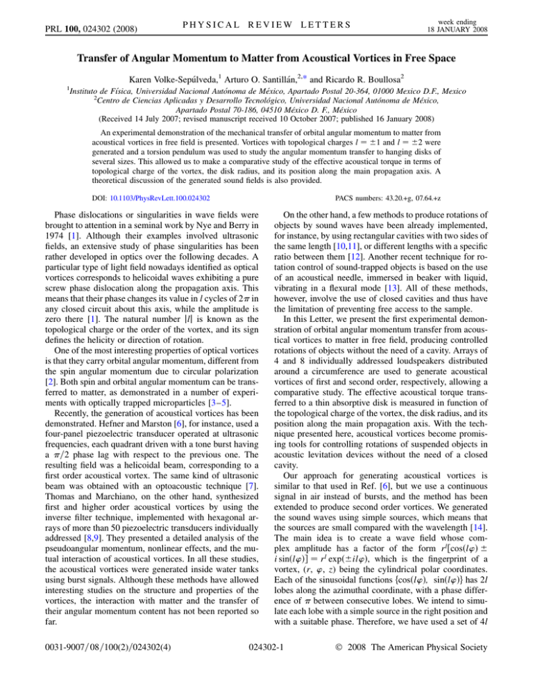
PRL 100, 024302 (2008) PHYSICAL REVIEW LETTERS week ending 18 JANUARY 2008 Transfer of Angular Momentum to Matter from Acoustical Vortices in Free Space Karen Volke-Sepúlveda,1 Arturo O. Santillán,2,* and Ricardo R. Boullosa2 1 Instituto de Fı́sica, Universidad Nacional Autónoma de México, Apartado Postal 20-364, 01000 Mexico D.F., Mexico 2 Centro de Ciencias Aplicadas y Desarrollo Tecnológico, Universidad Nacional Autónoma de México, Apartado Postal 70-186, 04510 México D. F., México (Received 14 July 2007; revised manuscript received 10 October 2007; published 16 January 2008) An experimental demonstration of the mechanical transfer of orbital angular momentum to matter from acoustical vortices in free field is presented. Vortices with topological charges l 1 and l 2 were generated and a torsion pendulum was used to study the angular momentum transfer to hanging disks of several sizes. This allowed us to make a comparative study of the effective acoustical torque in terms of topological charge of the vortex, the disk radius, and its position along the main propagation axis. A theoretical discussion of the generated sound fields is also provided. DOI: 10.1103/PhysRevLett.100.024302 PACS numbers: 43.20.+g, 07.64.+z Phase dislocations or singularities in wave fields were brought to attention in a seminal work by Nye and Berry in 1974 [1]. Although their examples involved ultrasonic fields, an extensive study of phase singularities has been rather developed in optics over the following decades. A particular type of light field nowadays identified as optical vortices corresponds to helicoidal waves exhibiting a pure screw phase dislocation along the propagation axis. This means that their phase changes its value in l cycles of 2 in any closed circuit about this axis, while the amplitude is zero there [1]. The natural number jlj is known as the topological charge or the order of the vortex, and its sign defines the helicity or direction of rotation. One of the most interesting properties of optical vortices is that they carry orbital angular momentum, different from the spin angular momentum due to circular polarization [2]. Both spin and orbital angular momentum can be transferred to matter, as demonstrated in a number of experiments with optically trapped microparticles [3–5]. Recently, the generation of acoustical vortices has been demonstrated. Hefner and Marston [6], for instance, used a four-panel piezoelectric transducer operated at ultrasonic frequencies, each quadrant driven with a tone burst having a =2 phase lag with respect to the previous one. The resulting field was a helicoidal beam, corresponding to a first order acoustical vortex. The same kind of ultrasonic beam was obtained with an optoacoustic technique [7]. Thomas and Marchiano, on the other hand, synthesized first and higher order acoustical vortices by using the inverse filter technique, implemented with hexagonal arrays of more than 50 piezoelectric transducers individually addressed [8,9]. They presented a detailed analysis of the pseudoangular momentum, nonlinear effects, and the mutual interaction of acoustical vortices. In all these studies, the acoustical vortices were generated inside water tanks using burst signals. Although these methods have allowed interesting studies on the structure and properties of the vortices, the interaction with matter and the transfer of their angular momentum content has not been reported so far. 0031-9007=08=100(2)=024302(4) On the other hand, a few methods to produce rotations of objects by sound waves have been already implemented, for instance, by using rectangular cavities with two sides of the same length [10,11], or different lengths with a specific ratio between them [12]. Another recent technique for rotation control of sound-trapped objects is based on the use of an acoustical needle, immersed in beaker with liquid, vibrating in a flexural mode [13]. All of these methods, however, involve the use of closed cavities and thus have the limitation of preventing free access to the sample. In this Letter, we present the first experimental demonstration of orbital angular momentum transfer from acoustical vortices to matter in free field, producing controlled rotations of objects without the need of a cavity. Arrays of 4 and 8 individually addressed loudspeakers distributed around a circumference are used to generate acoustical vortices of first and second order, respectively, allowing a comparative study. The effective acoustical torque transferred to a thin absorptive disk is measured in function of the topological charge of the vortex, the disk radius, and its position along the main propagation axis. With the technique presented here, acoustical vortices become promising tools for controlling rotations of suspended objects in acoustic levitation devices without the need of a closed cavity. Our approach for generating acoustical vortices is similar to that used in Ref. [6], but we use a continuous signal in air instead of bursts, and the method has been extended to produce second order vortices. We generated the sound waves using simple sources, which means that the sources are small compared with the wavelength [14]. The main idea is to create a wave field whose complex amplitude has a factor of the form rl cosl’ i sinl’ rl expil’, which is the fingerprint of a vortex, (r, ’, z) being the cylindrical polar coordinates. Each of the sinusoidal functions fcosl’; sinl’g has 2l lobes along the azimuthal coordinate, with a phase difference of between consecutive lobes. We intend to simulate each lobe with a simple source in the right position and with a suitable phase. Therefore, we have used a set of 4l 024302-1 © 2008 The American Physical Society PRL 100, 024302 (2008) week ending 18 JANUARY 2008 PHYSICAL REVIEW LETTERS (l 1, 2) simple sources of sound with frequency ! 2, evenly distributed around a circumference of radius a in the horizontal plane, each one having a phase lag of =2 in respect to its previous neighbor. The direction in which this phase lag increases will determine the vortex helicity. The vertical axis passing through the center of the circumference is set as the z axis. For a simple source, the radiated sound pressure has the form B expfikR !tg=R, with R the distance from the source to the receiver and B a com- plex constant [14]. Then, the total sound field generated under these conditions by the 4l simple sources can be expressed as pr; ’; z; t expi!t 4l X A0 n1 Rn expikRn expfin 1=2g; (1) where q Rn fr cos’ a cos2n 1=4lg2 fr sin’ a sin2n 1=4lg2 z2 : A0 =Rn is the pressure amplitude of the wave generated by the nth source, A0 being a real constant. Provided r2 a2 z2 and r a2 z2 =2a, expression (2) can be approximated as p 1 Rn a2 z2 1 2a2 z2 n 1 : (3) r2 2ra cos ’ 2l p By keeping just the first term Rn a2 z2 in the amplitude, we can rewrite Eq. (1) as A0 pr; ’; z; t p a2 z2 p kr2 exp i k a2 z2 p !t 2 a2 z2 4l X ikra n 1 exp p cos ’ 2l a 2 z2 n1 expfin 1=2g: Finally, by using the expansion expx 1 x x2 =2 for the first exponential term in the sum, and doing the sum explicitly, we arrive at pr; ’; z; t Az; akrl expfil’g kr2 exp i p !t ; 2 a2 z2 (4) for l 1; 2, where p l1 2A0 a l : Az;a exp i k a2 z2 p 2 l!a a2 z2 (5) The characteristic factor r expi’l explicitly appears in Eq. (4), corresponding to a vortex of order l. In the limit when z 0, Az; a takes its maximum value; for l 1, this could be compared with the field produced by orthogonal acoustic waves in a rectangular cavity when the phase lag between them is of =2 [10,12]. Within the linear acoustic regime, as corresponds to the case treated here, the velocity field in the transverse plane (2) can be written as 1 ~ p l ikr ^r i’ ^ p r^ ; v~ ? r? p i!0 i!0 r a2 z2 (6) where we used Eq. (4) for the pressure. 0 is the average ~? r ~ z^ @=@z, and r^ , ’, density of the medium, r ^ and z^ are the unit vectors in the respective directions. The plus (minus) sign stands for positive (negative) helicity. The angular momentum density along the z direction associated with this field is 2 l p Lz r r^ v~ ? ; (7) ! 0 c2 which turns out to be proportional to both the vortex topological charge and twice the acoustic potential energy density. When potential and kinetic energy densities are equal, Eq. (7) can be written as Lz !l ", where " represents the total energy density; this is in complete analogy with optical vortices [2], as discussed by other authors [6,8]. The acoustic intensity vector in the transverse plane, I? pv? , which represents the energy flux and is proportional to the linear momentum of the fluid, was calculated from the exact expression (1) for the pressure and the ~ ? p=i!0 . The result is corresponding velocity v~ ? r illustrated in Figs. 1(a) and 1(b), for the first and second order vortices, respectively, for z 5 cm, a 18:5 cm, and 26:4 cm. The energy circulation around the origin becomes apparent in both cases, though for the first order vortex, this pattern dissolves out for large r, but this is in agreement with the approximations assumed to obtain Eq. (4). The on-axis node, characteristic of any vortex, is related to the phase dislocation. According to Fig. 1 and Eq. (7), an object centered at the origin is expected to rotate in the same direction as the sound intensity; we demonstrated this fact in our experiments. The experimental setup is illustrated in Fig. 2(a). Eight drivers (for horn loudspeakers) were distributed around a circumference of radius a 18:5 cm; for generating the first order vortex, only four of them were activated (those at positions ’ 0, =2, , and 3=2). Each driver was connected to an independent channel of an audio amplifier, 024302-2 PRL 100, 024302 (2008) PHYSICAL REVIEW LETTERS week ending 18 JANUARY 2008 FIG. 2. (a) Experimental setup for the generation of acoustical vortices and transfer of angular momentum to a hanging disk in a torsion pendulum. (b) Diagram illustrating the operation system for each sound source. FIG. 1. Circulating acoustic intensity distribution in the transverse plane z 5 cm, calculated using Eq. (1): (a) for a first order acoustical vortex, and (b) for a second order vortex. and the amplifiers were in turn fed by using eight channels of an external sound card controlled with a PC [Fig. 2(b)]. In order to have a precise control of the phase differences and the pressure levels, each reproduction chain was individually characterized. By inverting the handedness of the =4 phase lag between consecutive sources around the circle, we could set the helicity of the vortex. A tube of length L was placed at the output of each driver, connecting it to the baffle [see Fig. 2(b)]; the opening in the baffle, with a diameter d 3:5 cm, behaves as an air piston. The resonance of the drivers was shifted up to 1300 Hz by using L 6 cm; the corresponding wavelength was 26.4 cm, which is large enough compared with the diameter, d 3:5 cm, of the individual openings in the baffle connecting to the drivers. This fact supports the assumption made in Eq. (1) that each opening can be taken as a simple source. The pressure level, measured along the z axis at 4 cm from the baffle with only one driver operating, corresponded to 124 dB. All the experiments were realized with the device inside an anechoic chamber. We scanned the pressure field (amplitude and phase) for each vortex and found a very good agreement with Eq. (1). For measuring the acoustic torque, we implemented a torsion pendulum with an optical fiber of high linear stiffness and a disk of radius r0 hanging at a high z0 over the baffle [see Fig. 2(a)]. Underneath the disk, on the baffle, we placed a 360 protractor with resolution of 1 , and we fixed a pin at the edge of the disk to make the angle measurements. We used six different disks of radii r0 2:7, 4, 5, 6, 7, and 8.1 cm, all of them made of acrylic (1.68 mm thick) and with both faces covered with a rubber foam layer (3.3 mm thick). The absorption coefficient and the acoustic impedance of the rubber foam on the acrylic were measured separately, giving values of 0.066 and 385 i2627 kg s1 m2 , respectively. When the sound field was generated, the disk rotated an angle to an equilibrium position where the acoustic torque generated by the vortex was exactly balanced by the opposite torque exerted by the torsion of the optical fiber. The torque in the torsion pendulum is given by , where 42 Idisk =T 2 is the rotational stiffness. Idisk r4o =2 is the moment of inertia of the disk; 0:21 g=cm2 is its mass surface density, and T is the oscillation period of the pendulum. The experimental results for the torque as a function of the disk radius are presented in Fig. 3 for l 1 and l 2. It was expected from Fig. 1 that the contribution to the total torque from the acoustic field on the disk would be small near the origin and more significant in outer regions. In fact, for disks of radii 2.7 and 4 cm, the torque is larger for 024302-3 week ending 18 JANUARY 2008 PHYSICAL REVIEW LETTERS PRL 100, 024302 (2008) 50 25 40 20 r = 4, l = 1 Torque (dn cm) Torque (dn cm) 0 l=1 l=2 30 20 0 r0 = 6, l = 1 r0 = 6, l = 2 15 10 5 10 0 2 r = 4, l = 2 3 4 5 6 7 8 0 0 9 FIG. 3 (color online). Variation of the torque in respect to the disk radius. The points represent experimental data, whereas the lines correspond to a fitted polynomial of degree (2l 1) in kr0 . the first order vortex than for the second order one, and the opposite occurs for disks with radius r0 > 4 cm; this can also be understood from Fig. 1. A theoretical calculation of the torque exerted by an acoustical vortex is not straightforward, since it is necessary to consider the effect of viscosity around the object [15], the scattered field [16], and the effect of acoustic impedance of the object surface. Nevertheless, a polynomial of degree (2l 1) in kr0 fits very well with the experimental data, as shown in Fig. 3. This is consistent with the fact that the magnitude of the acoustic intensity in the transverse plane, jI? j jpv? j, has this kind of dependence on r in the vortex zone, since p / krl and, neglecting the last term in Eq. (6), jv? j / ljpj=r. On the other hand, Fig. 4 shows the variation of the measured torque with z0 for disks of radii 4 and 6 cm, for l 1 and l 2 in each case. The maximum value of the torque occurs for the smallest value of z0 and then decreases monotonically in all cases, but it decreases faster for l 2. This is in agreement with Eq. (5), due to the p factor a= a2 z2 l1 . For the disk of radius r0 4 cm, the torque exerted by the first order vortex is larger for all z, as expected from Fig. 3. In our experiments, we verified that the direction of rotation of the disks was in agreement with the vortex helicity. Also, we checked that the magnitude of the acoustic torque depends linearly on the acoustic energy. However, for small values of z0 the larger disk (r0 8:1 cm) starts swinging in the case of the first order vortex when we increased the sound pressure level. This is due to the inhomogeneity of the sound field close to the baffle, which becomes apparent for large values of r. With the second order vortex this behavior was not observed. In conclusion, we have demonstrated that acoustical vortices can transfer angular momentum to matter under free field conditions. We presented a comparative study of the sound fields for the case of two topological charges, l 1 and l 2. Our results indicate that, for small objects, the 5 10 15 20 z (cm) Radius of the disk (cm) FIG. 4 (color online). Variation of the torque in respect to the high over the baffle, z0 , for two disks of radii r0 4 and 6 cm, for the two vortices l 1 and l 2 in each case. The points represent experimental data; the lines are just guides for the eye. torque exerted by the first order vortex is larger than that exerted by the second order one, but the opposite occurs when the object is larger than approximately 0:15. The authors aknowledge DGAPA-UNAM IN-114407. We are also grateful to the referees for important suggestions and to Professor Miles Padgett for the enrichening discussion when we heard about each other’s work. *[email protected] [1] J. F. Nye and M. V. Berry, Proc. R. Soc. A 336, 165 (1974). [2] L. Allen, M. W. Beijersbergen, R. J. C. Spreeuw, and J. P. Woerdman, Phys. Rev. A 45, 8185 (1992). [3] H. He, M. E. J. Friese, N. R. Heckenberg, and H. Rubinsztein-Dunlop, Phys. Rev. Lett. 75, 826 (1995). [4] N. B. Simpson, K. Dholakia, L. Allen, and M. J. Padgett, Opt. Lett. 22, 52 (1997). [5] V. Garces-Chavez, D. McGloin, M. J. Padgett, W. Dultz, H. Schmitzer, and K. Dholakia, Phys. Rev. Lett. 91, 093602 (2003). [6] B. T. Hefner and P. L. Marston, J. Acoust. Soc. Am. 106, 3313 (1999). [7] S. Gspan, A. Meyer, S. Bernet, and M. Ritsch-Marte, J. Acoust. Soc. Am. 115, 1142 (2004). [8] J. L. Thomas and R. Marchiano, Phys. Rev. Lett. 91, 244302 (2003). [9] R. Marchiano and J. L. Thomas, Phys. Rev. E 71, 066616 (2005). [10] T. G. Wang, H. Kanber, and I. Rudnick, Phys. Rev. Lett. 38, 128 (1977). [11] A. Biswas, E. W. Leung, and E. H. Trinh, J. Acoust. Soc. Am. 90, 1502 (1991). [12] M. R. Schroeder, Acta Acustica 75, 94 (1991). [13] J. Hu, C. Tay, Y. Cai, and J. Du, Appl. Phys. Lett. 87, 094104 (2005). [14] L. E. Kinsler et al., Fundamentals of Acoustics (John Wiley & Sons, New York, 2000), 4th ed., p. 175. [15] F. H. Busse and T. G. Wang, J. Acoust. Soc. Am. 69, 1634 (1981). [16] G. Maidanik, J. Acoust. Soc. Am. 30, 620 (1958). 024302-4
